At ValidExamDumps, we consistently monitor updates to the Juniper JN0-480 exam questions by Juniper. Whenever our team identifies changes in the exam questions,exam objectives, exam focus areas or in exam requirements, We immediately update our exam questions for both PDF and online practice exams. This commitment ensures our customers always have access to the most current and accurate questions. By preparing with these actual questions, our customers can successfully pass the Juniper Data Center, Specialist exam on their first attempt without needing additional materials or study guides.
Other certification materials providers often include outdated or removed questions by Juniper in their Juniper JN0-480 exam. These outdated questions lead to customers failing their Juniper Data Center, Specialist exam. In contrast, we ensure our questions bank includes only precise and up-to-date questions, guaranteeing their presence in your actual exam. Our main priority is your success in the Juniper JN0-480 exam, not profiting from selling obsolete exam questions in PDF or Online Practice Test.
Which statement about Juniper Apstra role-based access control is correct?
The following three statements are incorrect in this scenario:
You are working with a three-stage IP fabric using EBGP for peering.
In this scenario, which two actions are required to implement ECMP? (Choose two.)
To implement ECMP in IP fabric using EBGP, you need to enable BGP to install multiple equal-cost paths in the routing table and to advertise them to the peers. The following actions are required to achieve this:
B) Use a load balancing policy applied to BGP as an export policy. This is true because you need to apply a load balancing policy to BGP as an export policy to allow BGP to advertise multiple paths to the same destination to the peers. By default, BGP only advertises the best path to the peers, which prevents ECMP. A load balancing policy can be configured to match the desired routes and set the multipath attribute to true. This will enable BGP to advertise up to the maximum number of paths configured by the maximum-paths command. For example, the following configuration applies a load balancing policy to BGP as an export policy for the neighbor 10.10.10.1:
policy-statement load-balance { term 1 { from { route-filter 192.168.0.0/16 exact; } then { multipath; accept; } } } protocols { bgp { group ebgp { type external; neighbor 10.10.10.1 { export load-balance; } } } }
C) Use the multipath multiple-as BGP parameter. This is true because you need to enable the multipath multiple-as BGP parameter to allow BGP to install multiple paths from different autonomous systems in the routing table. By default, BGP only installs multiple paths from the same autonomous system, which limits ECMP. The multipath multiple-as parameter can be configured under the BGP group or neighbor level. This will enable BGP to install up to the maximum number of paths configured by the maximum-paths command. For example, the following configuration enables the multipath multiple-as parameter for the BGP group ebgp:
protocols { bgp { group ebgp { type external; multipath multiple-as; } } }
The following options are incorrect because:
A) Use a load balancing policy applied to the forwarding table as an export policy is wrong because applying a load balancing policy to the forwarding table does not affect the BGP advertisement or installation of multiple paths. A load balancing policy applied to the forwarding table only affects how the traffic is distributed among the multiple paths in the forwarding table. It does not enable ECMP in BGP.
D) Use a load balancing policy applied to BGP as an import policy is wrong because applying a load balancing policy to BGP as an import policy does not affect the BGP advertisement of multiple paths. A load balancing policy applied to BGP as an import policy only affects how the BGP routes are accepted or rejected from the peers. It does not enable ECMP in BGP.Reference:
IP Fabric Underlay Network Design and Implementation
Example: Configure an EVPN-VXLAN Centrally-Routed Bridging Fabric Using EBGP
Exhibit.
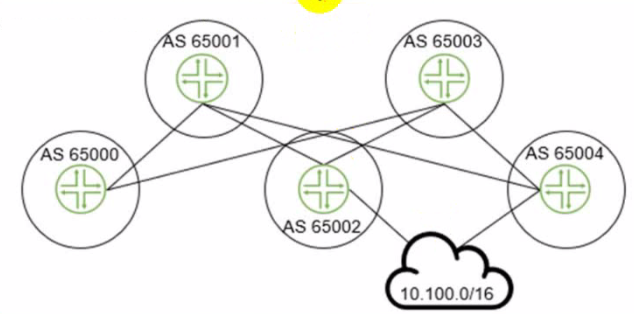
The 10.100.0.0/16 route is being advertised into your BGP IP fabric. ECMP load balancing has been properly enabled on all devices
In this scenario, how many routes will the leaf device in AS 65000 receive for the 10.100.0.0/16 prefix?
The leaf device in AS 65000 will receive three routes for the 10.100.0.0/16 prefix, one from each spine device in AS 65001, AS 65002, and AS 65003. Since ECMP load balancing is enabled, the leaf device will install all three routes in its routing table and distribute the traffic among them. The other options are incorrect because:
B) 1 is wrong because the leaf device will not receive only one route for the prefix. It will receive multiple routes from different spine devices and use ECMP to load balance among them.
C) 2 is wrong because the leaf device will not receive only two routes for the prefix. It will receive three routes from three spine devices, as explained above.
D) 4 is wrong because the leaf device will not receive four routes for the prefix. It will receive three routes from three spine devices, as explained above. The fourth spine device in AS 65004 is not directly connected to the leaf device and will not advertise the prefix to it.Reference:
IP Fabric Underlay Network Design and Implementation
BGP Multipath load sharing iBGP and eBGP
In the Juniper Apstra Ul. which two resource types would be created in the Resources menu? (Choose two.)
IPv4 (including Host IPv4)
IPv6 (including Host IPv6)
ASN (autonomous system number)
VNI (virtual network identifier)
VLAN (virtual local area network)
Integer (used for pool type VLAN in local pools in Freeform blueprints)
You have a virtual network that needs controlled access to other virtual networks in the same routing zone. Using the Juniper Apstra Ul. which feature would be used to accomplish this task?
A security policy is the feature that would be used to accomplish the task of controlling access to other virtual networks in the same routing zone using the Juniper Apstra UI. A security policy allows you to define rules that specify which traffic is allowed or denied between different virtual networks, IP endpoints, or routing zones. A security policy can be applied to one or more virtual networks in the same routing zone, and it can use various criteria to match the traffic, such as source and destination IP addresses, protocols, ports, or tags. A security policy can also support DHCP relay, which enables the forwarding of DHCP requests from one virtual network to another. The other options are incorrect because:
A) interface policy is wrong because an interface policy is a feature that allows you to configure the interface parameters for the devices in a blueprint, such as interface names, speeds, types, or descriptions. An interface policy does not affect the access control between different virtual networks in the same routing zone.
B) anti-affinity policy is wrong because an anti-affinity policy is a feature that allows you to prevent certain devices or logical devices from being placed in the same rack or leaf pair in a blueprint. An anti-affinity policy is used to enhance the availability and redundancy of the network, not to control the access between different virtual networks in the same routing zone.
C) routing policy is wrong because a routing policy is a feature that allows you to configure the routing parameters for the devices in a blueprint, such as routing protocols, autonomous system numbers, route filters, or route maps. A routing policy does not affect the access control between different virtual networks in the same routing zone, unless the routing policy is used to filter or modify the routes exchanged between different routing zones.Reference: